AI CNC programming: what is AI CAM and where does it help?
What AI CAM is, how it goes from STEP and drawing to a process plan, where it works well and where it falls short, the CAM programmer's role and who approves.
- Published:
- Author:
- Spindeo team
- 8 min read
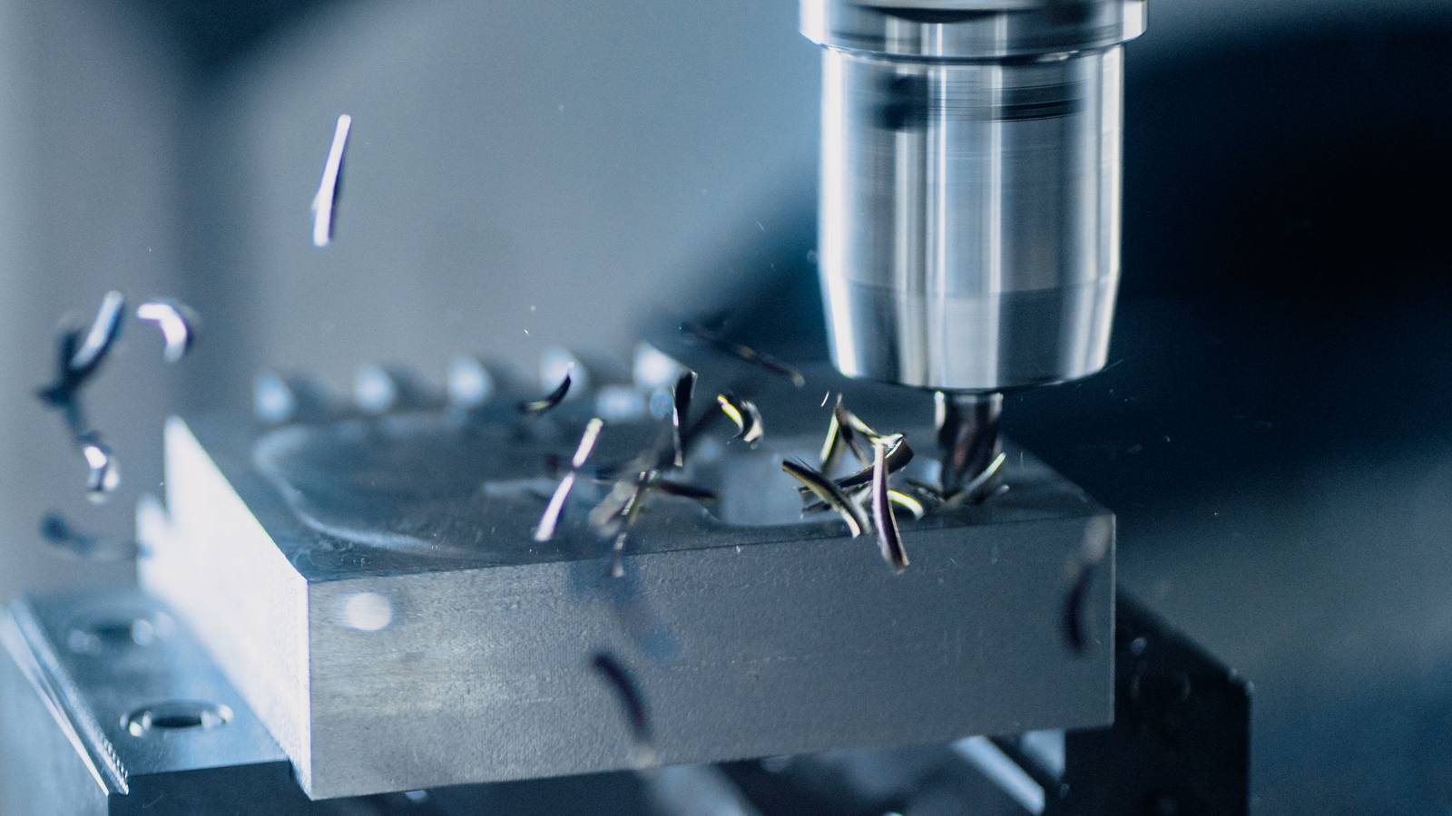
"AI writes CNC programs" gets two extreme reactions: "we don't need CAM programmers anymore" or "never send AI output to a machine". Both are wrong. This article explains what AI CAM actually does, the steps from a STEP file and drawing to a program on the machine, where it works and where it falls short, and why approval still rests with a person.
What is AI CAM
In classic CAM, the programmer opens the STEP model, defines the operations (face milling, pocketing, drilling, tapping), picks tool, speed, feed and strategy for each, the software calculates the toolpath, the programmer watches the simulation, and a post processor outputs G-code for the machine.
AI CAM does not replace one link in this chain; it gives the "thinking" to AI and the "calculating" to a classic CAM engine:
- AI builds the plan. It reads the STEP model and drawing, extracts features (pockets, holes, slots, threads, tolerances), and proposes operation sequence, tools and cutting data.
- The CAM engine calculates the toolpath. This part is not AI; it is geometry and must be exact. A classic engine generates the path from the AI's plan.
- Simulation and a checker review it. The path is simulated against part and stock. The checker tests defined rules: holder collisions, cutting below the part, speed and feed limits, how toleranced holes are machined.
- AI fixes what remains. If the checker reports findings, the AI revises the plan and the loop repeats.
- A person approves, then the G-code is released. No program goes out until the person watching the simulation approves it. The decision to send it to the machine, and the responsibility, belong to a person.
In short: the AI tries to think like a CAM programmer, but does not calculate or make the final call.
From STEP and drawing to plan
The AI has two inputs and needs both.
The STEP model provides the geometry: dimensions, surfaces, hole positions and diameters, pocket depths. But STEP has no tolerances, no surface finish, usually no threads, and often no material.
The drawing fills these gaps: material and hardness, tolerances on critical dimensions, thread callouts (M8, 1/4-20), surface finish symbols, heat treatment notes. The AI reads these and works them into the plan: for a toleranced hole, rough drilling followed by reaming or finish milling; for a thread, the tap drill size and the threading operation; for hard material, a lower cutting speed.
At planning, the user chooses three things: the machine (3 axis, 3+2, 4/5 axis mill or lathe), the stock (size and shape) and the tool mode. Tool mode has two options: the company's own tool list (the plan uses only tools on hand) or standard tools suggested by the AI. In a small shop the second gives a quick start; in serious production the first is essential, because a plan built on tools you don't have stays on paper.
Where it works well
Where AI CAM genuinely saves time:
- Prismatic parts. Parts dominated by pockets, slots, holes and threads, machined on 3 axis or 3+2. These are most of a machining shop's volume, and planning them is repetitive.
- Standard lathe work. OD turning, facing, grooving, holes, threads; two-sided parts and milling with live tooling.
- Quoting. A realistic machining time for a part not yet programmed. Answering "how many minutes is this part?" without tying up the programmer.
- Many similar parts. Programming 30 parts from the same family one by one is monotonous for a programmer and a good fit for AI.
- A saved history. Approved jobs stay on record with plans and programs; when the part comes back, nobody hunts for the program.
Where it falls short
An honest list, because overselling is this field's biggest problem:
- Complex freeform surfaces. For work that needs continuous 5 axis, such as molds, turbine blades or implants, an experienced programmer's strategy still decides. Continuous 4/5 axis support is limited, and it is not the primary tool for this work.
- Drawing quality. With hand-drawn, scanned, incomplete or contradictory drawings, the AI misreads or asks questions. Bad input, bad plan.
- Shop-specific knowledge. Experience like "this fixture chatters on that machine" or "this tool breaks often in that material" is not something the AI has. Unless defined as a rule, the checker doesn't know it either.
- Workholding design. How the part is clamped, and where it is held for the second operation, is a human decision. The AI assumes; the user verifies.
- Speed. A job takes minutes, not seconds; a part with many setups or axes can take half an hour, because the checker loop runs several times. For one simple part, an experienced programmer may still be faster.
The role of the operator and the CAM programmer
AI CAM does not put the CAM programmer out of work; it changes the job. The programmer no longer defines the toolpath for every pocket, but evaluates the plan, defines the rules and approves. The company's checker rules (which holder with which tool, which speed limit on which machine, which feed for which material) are the programmer's knowledge written down, applied automatically to every new program.
For the operator, the program's origin becomes visible: the simulation record, checker findings and approver are stored with the program. The answer to "who wrote this program, and based on what?" is in the library.
In a small shop without a full-time CAM programmer, AI CAM lets the owner or an experienced operator build a program. The responsibility for approval does not change; only the approver does.
Simulation and responsibility for approval
This is the most important part of the article. AI output is output: likely correct, not guaranteed. So there are two rules:
First: no G-code is released until the simulation has been watched. Even with no checker findings, the user watches the simulation start to finish. Material removal simulation shows how the stock is cut away; holder and part collisions, cutting below the part and leftover material show up here.
Second: the decision to send a program to the machine belongs to a person. The approved program is downloaded; whoever sends it to the machine, runs the first part in single block at reduced feed and measures it carries the responsibility. Classic CAM is the same; AI does not change this, and if anything calls for more care.
Know the checker's finding types: holder collision (tool stickout too short), cutting below the part (Z depth goes past the stock), speed and feed limits (machine capacity or a material rule), toleranced hole (cannot be drilled in a single pass), thread pilot hole (wrong diameter). An experienced programmer catches all of these by eye; the checker applies the same list every time, without tiring.
Output: machine controls
Once the plan is approved, G-code is generated separately for the selected control: Fanuc, Siemens Sinumerik and Heidenhain. If the same part runs on two different machines, you get two programs. On the first run, still check the program header, tool numbers and offset calls at the machine; every machine is set up a little differently.
Related articles: What is Spindeo? Production tracking for CNC machine shops, 10 questions for choosing production tracking software.
Frequently asked questions
Will AI CAM replace the CAM programmer?
No. It cuts planning time on repetitive prismatic work, but the programmer defines the rules, evaluates the plan and approves it. For complex freeform work, the programmer remains the primary tool.
Is it safe to send AI output straight to the machine?
No, no CAM output goes straight to the machine. The simulation is watched, the program approved, the first part run in single block at reduced feed and then measured. AI does not remove these steps; the checker only catches known error types earlier.
Which machines and controls are supported?
Milling: 3 axis, 3+2 and limited continuous 4/5 axis. Turning: two sides and live tooling. Controls: separate G-code for Fanuc, Siemens Sinumerik and Heidenhain. Mold and freeform work that needs continuous 5 axis is not the primary use case.
Does it work with only a STEP file and no drawing?
Yes, but with missing information: without tolerance, thread, material and surface data, the plan rests on general assumptions. If there are toleranced holes or threads, a drawing is required; otherwise this information is entered by hand.
Spindeo's AI CAM package implements the chain described in this article (plan from STEP and drawing, toolpath engine, simulation and checker findings, user approval, G-code for Fanuc, Siemens and Heidenhain); it includes 100 credits per month, with a 3 axis or lathe job using 10 credits, a 4/5 axis job 25 and a revision 5. If a job cannot be completed because of a CAM engine or connection error, the credits are refunded.